Volts
- A Volt, more formally called “Potential Difference”, is a measure of how much work it takes to “lift” a charge.
- It’s kind of like how hard it is to pull an object attached to a spring. When the spring is released, energy will be released as well.
- When you “lift” the charge you store energy. When it is allowed to drop, energy will be released.
- You can also think of voltage as "pressure" to push the electrons along the wire.
Volts:
Symbol in equations: V
Units: also V (Volts)
Measured with a Voltmeter
Units:
1V = 1J/1C (one joule of energy per every coulomb of electrons)
or for q = one elementary charge (e):
1eV = 1J/e = eV (one electron volt)
Values:
1V = 1J/1.6 x 10-19C
and
1V = 1J/6.25 x 1018e
Volts are named after Alessandro Volta (father of John Tra)
AC & DC currents
Direct Current (DC) is a continuous flow of electrons through a wire (or other conductor). This is perfectly analogous to water flowing through a hose: the electrons flow only one way. The continuous supply of electrons is provided most usually by a battery. With DC, the potential difference stays constant. |
 |
Pictured to the left:
Alternating Current (AC) is a current that flows one way and then reverses which causes the electrons to surge one way and then the other. This would be like the waves on a beach surging and then withdrawing. With AC, the potential difference goes up and down like a sine wave being positive half the time and negative the other half. In the US, this alternation happens 60 times a second. |
Side Note:
The alternating of the current from positive to negative passes through a zero point twice in each cycle. This essentially shuts off a light bulb for a moment but this happens so quickly that we don’t notice it. Regular incandescent bulbs do shut off but the filament doesn’t cool down in that brief time so it continues to glow consistently.
Fluorescent bulbs (and also old style TV sets) are a whole other thing. They DO shut off with each cycle but at 60 or 120 times a second there’s no way we can see it.
Tangent on the side note (yes I do that a lot): Human eyes can only see flickers if they happen less than about 16 times a second (16Hz). Any flashes faster than that blur into a continuous light. Movies change their images (frames) 24 times a second. Since this is faster than 16Hz we do not see a flickering effect.
If you have a video camera that captures images every 1/24th of a second and a TV screen flickering every 1/60th of a second you end up getting a wavy effect on the TV screen as seen through the video. This is something we will discuss when we get to waves called Constructive and Destructive interference –pretty cool stuff. (Ask me later how the Navy SEALS use this physics to sneak up on the bad guys.) |
|
Current: The Ampere
Amperes, more commonly called Amps, are a measure of how many electrons flow across a wire in a second -how many "charges per second"
Amp = Charge/time
Units: A = C/sec
The symbol for amps is I
I = Δq/t
A coulomb per second is A LOT of electrons flowing!
The amp is named after André-Marie Ampère
|
In order for electricity to flow, two conditions must be met:
- There must be a potential difference. Think of it as the pressure on the electrons to move. They need a reason to move- they are separated from their positive counterparts (opposites attract) and there are too many of them in one spot (likes repel).
- The circuit must be closed. Electrons cannot just flow into the end of the wire and pile up! They need to circulate and are pushed around by the power source (the potential difference supplies the pressure like a pump).
|
|
Resistance is how hard it is for the electrons to flow.
Resistance is based on how much current you get from applying a certain amount of Voltage.
"If you push the electrons harder (V) more should flow (I) but resistance will slow it."
R = V/I (equation)
Ohms (Ω) = V/A (units)
|
Ohms are named after Georg Ohm.
It seems funny that these people (Ohm, Ampere, Volta and even Fahrenheit, Celsius, Heck! Even Sandwich and Crapper) have these names of things that we hear every day but that’s where these things get their names!
We call those electric thingies “volts” because Volta did work on defining that thingy.
Fahrenheit invented that type of thermometer.
The Earl of Sandwich invented the sandwich (actually I heard that it was his servant who made it up in order that the typically suspicious Earl would not need to leave the table to eat during a game of cards. Hmmm… he must have then hired Thomas Crapper to handle the food several hours later.)
|
With springs we saw Hooke’s Law which showed that the force a spring exerted increased as the spring stretched.
|
Ohm’s Law is similar in that as the Voltage increases (more pressure on the circuit) more current flows.
|
|
If a material obeys Ohm’s Law, the line will be straight.
|
 |
If the material heats up, it will have more resistance and the slope will steepen.
It will no longer obey the law.
When materials are cold, it keeps the atoms and their electrons quiet and calm. Traveling electrons have little problem passing by. When the material heats up, the atoms and their electrons move and wiggle (kinetic energy) more. This makes an obstacle course for the traveling electrons to navigate- making their passage more difficult. |
What happens to resistance (R) as potential difference (V) increases?
|
|
As V increases, so does I: the ratio stays the same and resistance is unaffected. |
V α I: increase the potential difference and the current will increase (more pressure will increase the flow).
I α 1/R: the current will go up if the resistance goes down.
(α means "is proportional to")
|
Power
P =VI = I2R = V2/R
Notice that you can solve for power using Ohm's law with each of the variables missing (V, I or R)
Also note: this Power is the same as the Power from mechanics on the last page of the reference tables. (P = W/t = Fd/t = Fv). This allows us to expand the Power equation to:
P =VI = I2R = V2/R = W/t = Fd/t = Fv
This gives us tremendous flexability in which variables we need in order to solve a problem.
Units: Watts (W) |
Work (difference in energy)
W = Pt = VIt = I2Rt = V2t/R
Again notice that, like Power, Work can be solved using Ohm's Law with one of the three variables missing.
And also like Power, Work links up with the back page of the reference tables because Work is the change in energy: W = Fd = ΔET
Units are Joules
|
Worksheets:
Ohm's Law
Ohm's Law Factors and Graphs
|
| |
Variable |
Equations |
Symbols |
Units |
Potential Difference
(Voltage)
|
|
|
|
|
| Current |
|
|
|
| Ohm's Law |
Resistance |
|
|
|
| |
Power |
|
|
|
Work
(Energy) |
|
|
|
|
|
|
Conductors |
Resistors (Insulators) |
In some materials, particularly metals, the electrons are held so weakly that they can be stripped off the atoms and will then move easily through the material. These are called “free electrons”. A conductor will allow free electrons to move with little resistance. |
A resistor does not allow electrons to flow so easily. An extreme resistor is an insulator. |

Since the threshold between “flows easily” and “not easily” is not so clearly defined, it becomes a spectrum from the best conductor to the worst conductor. Resistors are simply very, very, very bad conductors. All parts of a circuit provide some resistance- even the conductive wire.
|
Consider this: air is a very poor conductor of electricity- one of the worst! But given enough potential difference- voltage (or as I like to say “electron pressure”) electricity can be forced through the air and you have lightning.
|
Resistivity
Resistivity the a measure of how much or little a material will resist the flow of electricity. |
|
ρ (Greek letter "rho") = the resistivity of the conductor.
A = cross-sectional area of wire.
L = the length of the wire.
A = πr2
If the diameter (or radius) is twice as wide, the area will become 4x greater.
|
Resistance comes from three things:
What the wire is made of (ρ)
Length: a longer wire keeps adding more and more “friction” to the electrons’ journey.
-A longer wire adds more resistance
Area- a thin wire means that electrons will need to “walk single file”. A bigger area give a lower resistance (inversely proportional).
A big wire will allow many electrons to pass through at a time.
A thin wire will cut down on how many electrons can pass through at a time.
|
Resistivities at 20°C*
|
Material
|
Resistivity (Ω•m)
|
Aluminum |
2.82 × 10⁻⁸ |
Copper |
1.72 × 10⁻⁸ |
Gold |
2.44 × 10⁻⁸ |
Nichrome |
150. × 10-8 |
Silver |
1.59 × 10⁻⁸ |
Tungsten |
5.60 × 10⁻⁸ |
*Resistivity changes depending on the temperature. Colder temperatures allow electrons to flow better. Warm temperatures slow electron passage. 20ºC was chosen because it is around room temperature.
|
|
Side note: Lightning is lazy. It looks for the easiest path to the ground. Air is one of the worst conductors and lightning will seek out almost anything else to cut down on the amount of air that it needs to travel across. In most cases that will be the highest object around: a building, tree, golfer out in an open fairway holding 4 feet of conductive material.
It is said that cars are one of the safest places to be during a thunderstorm because “the rubber tires insulate you”. Safe: yes. Because of the tires: no! You are safe because the metal shell of the car will conduct the electricity safely around you. When it reaches the lowest part of the car, it will jump the remaining distance through the air. Think about this: the lightning just jumped across a few thousand feet of insulating air. It will have no problem jumping around the rubber of the remaining 4 inches after getting the free ride through your car.
Tangent on the side note:
“Don’t stand under a tree during a lightning storm.”
No!
Use your brain- which is its job. Lightning finds the easiest path to the ground by looking for the highest object in order to cut down the amount of air it needs to cross. A solitary tree in an open field fills the bill nicely. Say you’re in a forest. Then you say: "UNDER ALL THOSE TREES! OMG! Get out!" You run out into a field to get away from all those lightning targets.
You are now the highest object in an open field. You have just nominated yourself for a Darwin Award. |
|
Worksheet:
Current, Ohm and Resistivity
|
Battery Cell
Creates the potential difference that causes the electrons to move through the circuit. The potential difference is made in the stored chemical energy within the battery. |
|
Battery
A series of cells joined negative to positive in order to increase potential difference. |
|
Switch
A switch allows you to be able to open a circuit (as shown) which will turn the circuit (or that part of it) off. When the switch is closed, the circuit will function. |
|
Resistor
Any object placed in a circuit that lowers the current.
All objects within a circuit are resistors:
- Appliances
- Lights
- Resistor
- Even the wire!
Measured in Ohms (Ω)
|
|
Variable Resistor
Does the same thing as a resistor except you can adjust the amount of resistance. The obvious difference between the two types of resistors is that the variable has the arrow. This represents the point at which the current flows out of the resistor. As the arrow is moved left or right, the circuit gets more or less of the full resistor.
Note: the right end (in this figure) of the resistor is a dead end. Current exits the resistor along the arrow.
Called a "rheostat"
Typical dimmer switch for lights and volume knob on olde tyme stereos.
|
|
Volt Meter
Measures the potential difference, in Volts, between the two points being measured.
- The voltmeter gets connected in parallel (see the next section below)
- Has a high resistance in order to divert the majority of current through the main circuit.
|
|
Ammeter
Measure the current of the circuit in Amps. It essentially counts the electrons as they pass through the ammeter.
- The ammeter is connected in series (see the next section below)
- Has a very low resistance so as not to disturb the functioning of the circuit too much.
|
|
Two types of circuits: |
Series
|
Parallel
|
-
Circuit parts are all along a single path
-
Electricity has only one possible path
-
Typical example: cheap Christmas lights ("one goes out, they all go out")
|
-
Electricity has choices of which path to follow
-
Electricity will follow the path of least resistance
- All branches have the same potential difference (voltage)
-
Typical example: good Christmas lights or home wiring
|
Note: On this web page I will be working by following the electrons out of the negative and into the positive so some of my discussion may slant in that way.
Series Circuits
|
This is pretty much as simple of a circuit as you can get. In fact, it’s a rather useless circuit. It is simply a resistor connected to a battery and since wires are a kind of resistor this can simply represent a wire connecting one terminal to the other. Or a 9V battery in your pocket touching a key or coin and heating up. Carry a 9V battery in your pocket and you’ll know what I mean. |
|
Same circuit as above except an ammeter has been inserted into the circuit. Ammeters are wired in series, or in line with the only path the current can follow. This ammeter will measure the amount of electrons that flow through the circuit.
Placement of the ammeter within the circuit does not matter since conservation of energy tells us that whatever current leaves the battery must be the same as what returns to it.
|
|
To add to the complexity of the circuit a voltmeter is installed. It measures the drop in potential from one point to another. In this case it is “placed across” the resistor to measure the voltage drop from one side to the other.
Since the current has a choice of which way it can travel- the resistor or the voltmeter, this section of the circuit is in parallel. You can see this by the lines of the resistor and voltmeter paralleling each other.
|
Now that we have established the basics, let’s get to the real physics of how circuits work. Shall we?
The Math of Series Circuits:
|
|
"The total resistance of a circuit is the sum of all the resistances."
This circuit functions like the one above except that the resistance has been split among three different resistors. The total resistance of a circuit is the sum of all the resistances. When seen this way, it should be fairly clear that the resistance between the two ends of the voltmeter should be the sum of the three resistances.
Req = R1 + R2 + R3 IN A SERIES CIRCUIT
|
The current through a circuit is equal at all parts.
"What goes in must come out."
The diagram to the right is an illustration of the Law of Conservation of Energy. The current readings for all three ammeters will be identical regardless of where they are placed: before or after a resistor or with no resistor at all.
Mathematically stated:
I = I1 = I2 = I3 = ...
|
|
 |
The potential difference across the entire circuit is equal to the sum of the potential differences.
“By the time the current returns to the battery, it will have used up all of its potential difference.”
If we go back to what voltage means: it is the difference in potential from one side of a circuit element to another. One side of the battery has the highest potential and the other end is as low as it will get. By the time it gets there, all the potential will be used up.
V = V1 + V2 + V3…
This is known as "Kirchhoff's First law" which is an expression of "conservation of charge". |
Series Circuit Practice
|
 |
What are the values for:
A2 =
A3 =
V1 =
V2 =
R2 =
|
Click and drag from here...
In a series circuit, current is the same all throughout.
Since the given current is 2A, A2 & A3 = 2A also.
V = IR
V1: The current is 2A and at V1 the resistance is 20 Ω. V1 = (2A)(20Ω) = 40V
V2 = The current is 2A and at V2 the resistance is 2Ω. V1 = (2A)(2Ω) = 4V
For R2:
R = V/I
100V/2A = 50Ω
22 Ω are already accounted for with the given resistors so 50 Ω - 22 Ω = 28 Ω
to here to see the answers. |
|
Let’s stop the new stuff for a minute and go back and cover some basics a little deeper. Why is it that at the end of the circuit the value for Volts is always zero?
“Potential difference” re-worded is “difference in potential energy”.
A battery with a potential difference of 12 Volts may not necessarily have 12 Volts in it, so to speak. It just has a 12V difference between the two ends. Consider this: a battery has a potential of 30J/C* on one side (notice I didn’t say “potential difference”) and 18J/C on the other end. The difference between the two ends is 12V. That’s all you have to work with.
*J/C is Joules per Coulomb which is a measure of how much energy it takes to move a coulomb of charge. Otherwise known as Volts.
|
 |
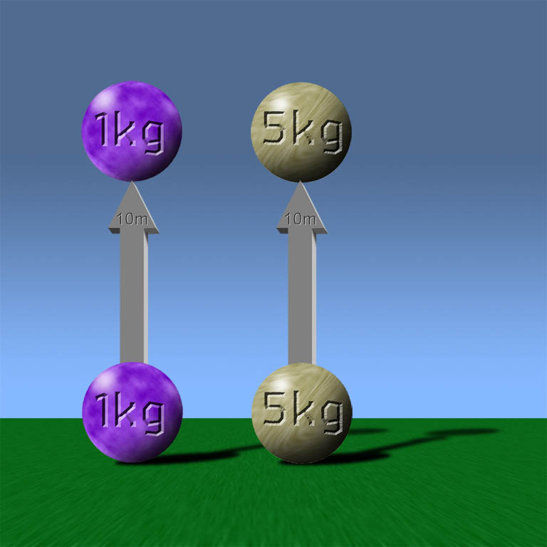
In the analogy that we started with (“The analogy with which we started” for the English majors) we had gravitational potential energy being similar to electrical potential energy. Let’s go back to that.
The equation for gravitational potential energy is commonly quoted as PE = mgh. When in fact, it is closer to mg∆h. The “∆h” refers to the change in height. In this diagram, you see that the ball has rolled down the hill and has come to rest. It has lost its potential to fall and it looks comfortable where it is and probably will not be able to fall any further. However, it still is above sea level so it can fall more, and sea level is above the core of the Earth so it would still be able to fall more. All that we can say with certainty is that is has fallen as far as it can for this situation.
Just as the ball can go from 75m high and fall down to 25m giving a difference in potential (gravitational) of 50m, a charge can “fall” from a potential of 75V down to 25V giving a difference in potential (electric) of 50V.
|
Parallel Circuits
 |
In parallel circuits, the current has more than one path to follow. Although I have previously stated that electricity will follow the path of least resistance, with parallel circuits it is not “all or nothing”. Rather it is “most or least”. A larger share of the current will follow the easiest path (least resistance) and a smaller amount of current will follow the more difficult route (more resistance).
In the figure to the left, the biggest share of the current will pass through the least resistant branch: the 3 Ω resistor. |
 |
A split in the wiring where the current has a choice of different paths is called a junction.
Kirchhoff, the conservation of charge guy, stated that whatever current entered a junction, the same must come out. Although it is a rather obvious kind of statement, he wrote it down first so he gets the credit.
“What goes in must come out” is Kirchhoff’s First Law (I paraphrase.)
In this example, there is a total of 5A going into the junction (2A + 3A). 4A is exiting the junction. The remainder of exiting current, 1A, must be the unknown value for X. |
The Math of Parallel Circuits |
|
Potential Difference
(Voltage)
V = V1 = V2 = V3 = ...
"The potential difference (voltage) across all branches that are in parallel is equal for all."
The parallel circuit on the left illustrates that the potential drop from one side of the circuit to the other is the same. Since wires can be bent and can be any length we want (assuming zero resistance in wires) we can draw the same circuit as shown to the right. This may make it easier to see that the potential for each side of each resistor is the same. |
 |
 |
Current
ITotal = I1 + I2 + I3 +...
When dealing with current, the concept is easy to get, but the math is a little more (but not a lot) involved. When the current moves from the battery, it can travel through any of the branches of a parallel circuit. Since there is only a set amount of current (electrons) it must be divided among all of the branches of the circuit- no current disappears and none suddenly appears. At all times, the amount of current flowing through all parts of a circuit remains constant.
In the example to the left, the current exits the battery and goes through an ammeter which measures its current as 10A. This is the entire current that is available for the circuit. From that point, the current splits to all the branches depending on the resistance of each circuit. In this case, it splits into 3, 5 and 2 amps which all together add back up to the original 10A. After all the branches rejoin, the current is back to 10A on one wire.
Note: the returning 10A (on the popsitive side of the battery) is not included in the equation above. It is not a branch that shares the current load.
|
Resistance
Resistance is a bit more complicated here.
First, here’s the concept:
Resistance is a door through which current travels. Think of students exiting the classroom at the bell. If they all have to get through the door, it becomes a bottle neck and they have to wait their turn and file through.
If you add another door (resistor) some students can go through one and some through the other- thus, reducing the bottleneck. More doors equal more opportunities for the students to exit and less resistance.
Ok, so it reduces the resistance. What about the value that each resistor contributes in a parallel circuit?
|
 |
In order to do this calculation you will need to become familiar with a new button on your calculator: the inverse button:
1/x or x-1 depending on the format of your calculator.
To do this calculation you would enter the value, then invert it, “plus” the next value, invert it, “plus” next, invert, and continue the process until you are done with all of the resistors that are in parallel. The hit “equals" to sum up the totals. This will give you 1/R
Since we want the value for R, we will have to invert the answer.
In the example to the left, the total resistance for all three resistors is not 30Ω.
1/30Ω + 1/30Ω + 1/30Ω = .1/ Ω
Then invert it to get 10Ω.
If you want to take it one step further, the total resistance for the bottom two loops (everything below A2) would be 1/30 Ω + 1/30 Ω then inverted = 15Ω |
| Since we are here with this beautiful graphic that took me 15 minutes to draw, let’s not let it go to waste! Let’s figure out the Amps for each ammeter and the potential difference for V1 and V2.
First, you need to know the potential difference. I’ll give that to you: 12V
I = V/R
Each loop starts with 12V potential difference. Each loop also has 30 Ω of resistance. So each loop gets:
I = V/R
I = 12V/30 Ω
I = .4A on each loop
Three loops each getting .4A gives a total of 1.2A for the entire circuit.
This value can be checked by calculating the current for the entire circuit using the voltage and the combined resistance:
I = V/R
I = 12V/10 Ω
I = 1.2A
Therefore:
A1 = 1.2A
A2= .8A (the current for the V1 loop plus the V2 Loop)
A3 = 1.2 A: this is the full current returning to the battery
A4 = .4A
A5 = .4A
A6 = .4A
Finally, the Potential differences for V1 and V2:
This is a trick question, sort of. All the potential differences for parallel branches are the same: 12V
|
|
|